Working in ultra-high vacuum (UHV) is a pain in the ass. The idea is that by achieving such a high-quality vacuum (having something like twenty thousand billion times less gas atoms per unit volume flying around than in air), we can perform atomically well-defined experiments without all the airborne junk and hopefully learn something about physics at the atomic and molecular scale.
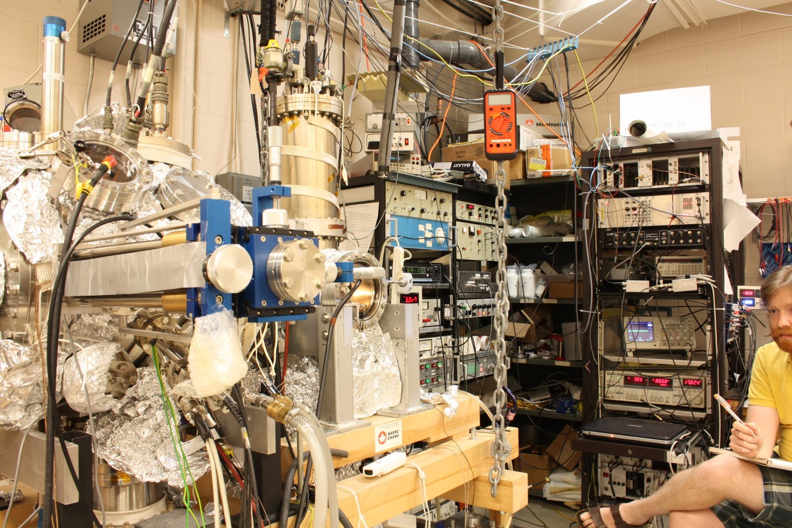 |
| Ultra high vacuum system, named Dolores, on the left. Me on the right. We often fight. |
But when things go wrong, there is a lot of down-time. This post aims to share a simple electronic circuit that can help to relieve some of the pains associated with equipment failure.
A common type of pump used to achieve UHV is the turbomolecular pump, which looks very similar to an aircraft jet engine. Its rotor turns really really fast (~1000Hz - yes, revolutions per second!) in order to transfer momentum to the gas particles in vacuum such that they are propelled toward its exit. The turbo pump must itself be connected to a vacuum pump (known as a roughing pump, or forevacuum pump). This ensures that the pressure throughout the turbo pump is sufficiently low to reduce viscous drag on the rotors.
Unfortunately, if something bad happens to the roughing pump, like it overheats, seizes, leaks oil, etc. the turbo pump might get damaged. And in the case of an expensive magnetically levitated bearing pump, it might cost 8 weeks of research time and $25000 to replace. Problems associated with roughing pumps have occurred twice in our lab in the last decade and have necessitated a turbo pump replacement.
Naturally, it would be nice to avoid such incidents in the future. This is why I put together a simple, robust analog circuit to monitor the forevacuum pressure and shut down the turbo pump and close the vacuum valves if the pressure goes bad. It only costs $50 to build, and I think I wrote a nice pedagogically rigorous report on "how to do it" so that you can learn something about electronics, and build it step-by-step. Unfortunately, the Review of Scientific Instruments or Journal of Vacuum Science and Technology A won't even publish it as a "shop note" (yeah ok, I understand it's not "novel science", but it's useful!).
So, after a double editor rejection, I am unleashing it upon the internet. Because somewhere, there is another poor suffering grad student working on a complex UHV system who might want to put together something like this as an investment toward their supervisor's wallet's well-being, their expedited graduation (freedom!), and their mental health.
Oh and by the way, it saved my ass when this happened:
You'll find a very detailed description of the electronic circuit below, and more stuff including a parts list, below that.
 |
| Turbomolecular pump innards, from US Patent EP0522603A1 |
Unfortunately, if something bad happens to the roughing pump, like it overheats, seizes, leaks oil, etc. the turbo pump might get damaged. And in the case of an expensive magnetically levitated bearing pump, it might cost 8 weeks of research time and $25000 to replace. Problems associated with roughing pumps have occurred twice in our lab in the last decade and have necessitated a turbo pump replacement.
Naturally, it would be nice to avoid such incidents in the future. This is why I put together a simple, robust analog circuit to monitor the forevacuum pressure and shut down the turbo pump and close the vacuum valves if the pressure goes bad. It only costs $50 to build, and I think I wrote a nice pedagogically rigorous report on "how to do it" so that you can learn something about electronics, and build it step-by-step. Unfortunately, the Review of Scientific Instruments or Journal of Vacuum Science and Technology A won't even publish it as a "shop note" (yeah ok, I understand it's not "novel science", but it's useful!).
So, after a double editor rejection, I am unleashing it upon the internet. Because somewhere, there is another poor suffering grad student working on a complex UHV system who might want to put together something like this as an investment toward their supervisor's wallet's well-being, their expedited graduation (freedom!), and their mental health.
Oh and by the way, it saved my ass when this happened:
 |
| KF flange that broke in the forevacuum line overnight, totally randomly. Interlock to the rescue. |
You'll find a very detailed description of the electronic circuit below, and more stuff including a parts list, below that.
ABSTRACT
We describe the design and operation of a simple analog circuit which can be implemented in various applications where a process should be shut off if a threshold value of an analog signal is reached. The threshold value, hysteresis, and trigger direction can be easily set. Judicious analog design ensures reliable operation, and versatile functionality is built in without the need for programmable microcontrollers. A PCB layout is provided along with a component list for quick assembly. We use the circuit in our lab to monitor forevacuum pressure to protect turbomolecular pumps and UHV pressure during sample annealing.
Safe interlocking
of a UHV system is desirable to avoid damage from inevitable disruptions coming
from equipment failure or power outages [1,2]. In the operation of our surface science UHV
system, we have come across situations when it would be desirable to abort a
processes automatically based on UHV or forevacuum pressure.
In this shop note,
we discuss a circuit that was recently designed and implemented to monitor the
pressure of a forevacuum line using the common analog output of a pressure
gauge. It protects a sensitive magnetic
bearing turbomolecular pump against a possible rotary vane roughing pump
failure (which has proved to be problematic twice in the last decade of
operation, once causing several thousand dollars of damage). If the forevacuum line pressure exceeds
1.5x10⁻² mbar, the circuit described here is used to close the UHV
and forevacuum valves around the pump, and the pump is stopped. We also use this circuit to monitor the UHV
pressure in our preparation chamber so that sample annealing is stopped if the
pressure exceeds 6x10⁻⁸ Torr.
This allows us to run a filament overnight without worrying about vacuum
malfunction.
The circuit is
designed to close a relay during “normal” operation so that current can flow to
the device or filament. If the control
signal passes a trigger value, the relay will open and halt the current
flow. The circuit can be configured for
“normal” operation when the input voltage is lower than a trigger (normal low configuration), or higher (normal high configuration) than a
trigger. The trigger value is easily set
by a potentiometer. One resistor
modifies the hysteresis trigger value for the return of the control signal to its
normal state. The circuit can also be
configured for single-shot mode so
that the relay will not close again until the user activates a “set”
switch. A bypass switch is provided to
keep the relay closed regardless of the control signal value. In addition, if the input signal is
unplugged, the relay will open after a time delay. This functionally simple, computer-less,
analog solution is reliable, robust, and easy to construct.
The implementation
of the aforementioned features will be described in detail with additional
information in supplementary material (following this text). In the following description of its design,
we refer to the sections of the circuit that are labeled and circled by dashed
lines in Figure 1.
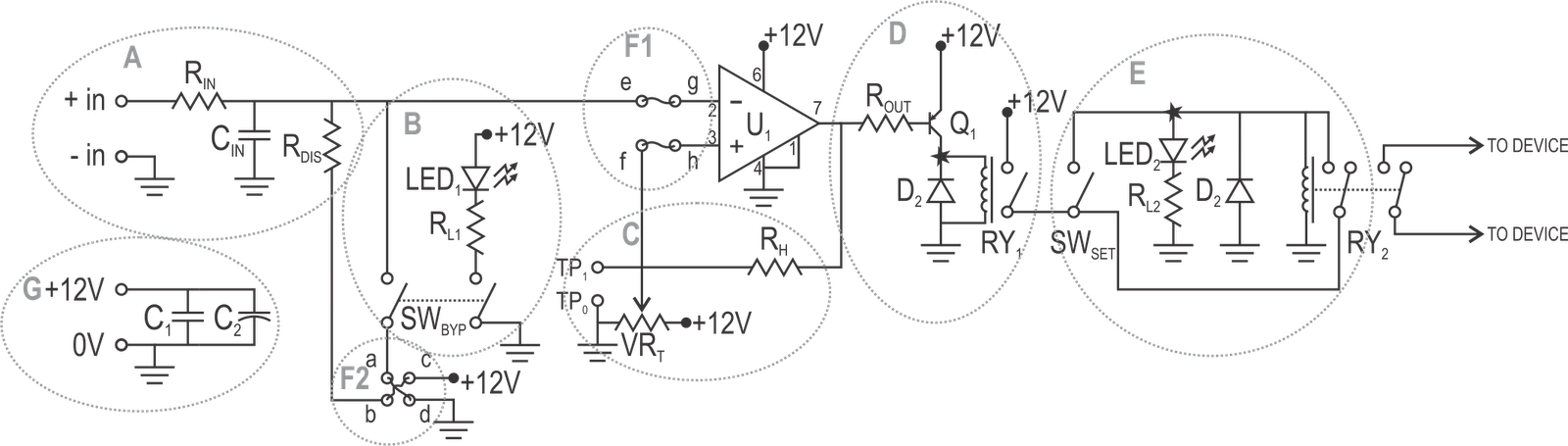 |
| Figure 1: Circuit diagram of the interlock circuit. Circled sections are described individually in detail in the text. |
In section A, the
combination of RIN and CIN assume the function of a
low-pass filter for the control signal with corner frequency fIN =
1/(2πRINCIN) (assuming RIN << RDIS). RDIS is a resistor used to disable
the output by pulling the input in the opposite direction to the “normal” state
in case the control signal is unplugged.
The disable function occurs after a characteristic time τIN =
RDISCIN (the exact time also depends on the threshold
level being used). We use RIN
= 100kΩ, CIN = 1µF, and RDIS = 100MΩ for a filter
frequency of ~1.6 Hz and automatic disable time of ~100s.
The bypass switch,
SWBYP, is implemented in section B with a DPDT switch used to impose
a “normal” state regardless of the input voltage. The other pole of the switch is used to turn
on a LED to indicate the status of the bypass (RLED = 2.49kΩ for a
current of ~4mA, assuming a 2V diode drop).
Section C contains
the trigger setting potentiometer, VRT, and a hysteresis resistor RH. The hysteresis means that the trigger voltage
seen by the comparator changes based on the state of the output. If R1 is the resistance between
the potentiometer wiper and ground, and R2 is the resistance between
the wiper and the +12V rail, then the upper and lower thresholds are given by Vupper
= 12V·R1/(R1+R2||RH), and Vlower
= 12V·R1||RH/(R1||RH+R2),
where || denotes the parallel combined resistance. For a 100kΩ potentiometer centered at R1
= R2 = 50kΩ, a hysteresis resistor of RH = 220kΩ,
the upper and lower thresholds are ~6.6V and ~5.4V. Test points TP1 and TP2
allow for easy testing of these thresholds using a multimeter. This is described later.
In section D, a
2N3906 transistor (Q1) is driven by the output of the LM311
comparator (U1) through ROUT = 10k which powers a relay,
RY1. A 1N4004 flyback diode D1
protects against the back EMF generated when switching off the relay coil. RY1 is used for the single-shot configuration. If single-shot
operation is not needed, RY1 can be omitted, and the point indicated
by a star in section D should be connected by a wire to the corresponding star
point in section E.
The output relay,
RY2 is located in section E.
If the relay is energized, LED2 is illuminated (current
limited by RLED2 = 2.5kΩ). In
the case that single-shot mode is not
needed, the set switch, SWSET, can be eliminated. The board mounted relay can switch a device
(up to 8A) soldered directly to the pins labeled DEV in Figure 2(a). If a higher current is needed, an off-board
relay coil can be attached to the auxiliary outputs labeled RY2 in Figure 2(a).
Sections F1 and F2
set the normal high or normal low configuration of the
board. If “normal” operation should
occur with a signal lower than the threshold, the circuit should be wired as
per the normal low configuration
shown in Figure 1, making the following connections: a-d, b-c, e-g, and
f-h. These correspond to the blue and
red dashed connections in Figure 2(a), labeled a through h. If normal
high is needed, the connections should be made as: a-c, b-d, e-h, and f-g,
which is shown in Figure 2(b). These
connections switch the direction in which the disable and bypass features work,
as well as the order of the inputs to the comparator. We use a normal
low configuration for our forevacuum pressure monitors with a Balzers
TPG300, and a normal high configuration
for our UHV pressure monitor with a Lesker IG4400.
 |
| Figure 2: Printed circuit board layout (actual dimensions: 36x122mm). (a) Copper traces shown in black with component overlay (normal low configuration shown); (b) assembled circuit board (normal high configuration shown) |
Power supply
smoothing capacitors C1 = 22µF, and C2 = 0.1µF are
included in section G.
We produced the
single-sided circuit board shown in Figure 2(a) in our lab using Pulsar Toner
Transfer Paper.
At the time of
assembly, the circuit must be configured for
normal high or normal low operation. If it is not being configured for single shot operation, the points marked
by a star need to be connected by a wire and the optional components listed in
the parts list (following this text) can be omitted.
The threshold
should be set in the following way:
- Connect a multimeter to the test points labeled TP0 (common) and TP1 (threshold voltage).
- Connect a wire to the +in terminal block.
- Apply DC power to the circuit
- By touching the +in wire to 0V or 12V (the screws on the power terminal block are ideal for this), the state of the relay will switch, and the multimeter will read the threshold voltages.
- Adjust the potentiometer and RH value (we mount RH on IC pins for easy replacement) until the desired thresholds are achieved.
In summary, this
simple, versatile interlock circuit is easy to build and configure for a
variety of applications. It has improved
the safety and robustness of our existing UHV system, and has reduced the risks
involved with roughing pump failure and unattended sample annealing.
[1] J. P. Saint-Germain, G. Abel, and B. L. Stansfield, J. Vac. Sci. Tech. A 4, 2391 (1986).
[2] J. A. Polta and P. A. Thiel, J. Vac. Sci. Tech. A 5, 386 (1987).
SUPPLEMENTARY INFORMATION
Standalone unit
We have integrated two of these circuit boards into a larger rack-mounted interlock panel to add pressure monitoring functionality. Another board was assembled as a standalone unit, shown below, for annealing samples. All the parts, except wires and mounting screws, are specified in the parts list.
Parts List
The following table summarizes the parts used in the
interlock circuit, along with their corresponding Digikey Part # and the cost
of the part in Canadian dollars at the time of writing.
The parts indicated as optional are those that are used for
the single shot operation and can be
omitted if un-needed.
Part
|
Function
|
Description
|
Digikey
Part #
|
Cost
|
PCB
COMPONENTS
|
||||
RIN
|
Input Resistor
|
100k resistor
|
CF14JT100KCT-ND
|
$0.09
|
CIN
|
Input Capacitor
|
1uF, 63VDC, film capacitor
|
399-5860-ND
|
$0.46
|
RDIS
|
Disable Resistor
|
100M resistor
|
RNX100MBCT-ND
|
$1.86
|
SWBYP
|
Bypass Switch
|
On-On DPDT switch
|
450-1533-ND
|
$2.98
|
LED1
|
Bypass enable LED
|
Orange 3mm LED
|
754-1588-ND
|
$0.33
|
RLED1
|
LED current limiting resistor
|
2.49k resistor
|
RNF14FTD2K49CT-ND
|
$0.16
|
VRT
|
Threshold potentiometer
|
100k trimmer potentiometer
|
3296W-104LF-ND
|
$2.92
|
RH
|
Hysteresis resistor
|
220k resistor
|
CF14JT220KCT-ND
|
$0.09
|
U1
|
Comparator
|
LM311 comparator 8DIP package
|
497-1570-5-ND
|
$0.60
|
ROUT
|
Comparator output resistor
|
10k resistor
|
CF14JT10K0CT-ND
|
$0.09
|
Q1
|
Relay driving transistor
|
2N3906
|
2N3906FS-ND
|
$0.21
|
D1
|
Flyback diode (optional)
|
1N4004
|
1N4004FSCT-ND
|
$0.16
|
RY1
|
Set switch relay (optional)
|
SPDT 12V relay
|
PB1018-ND
|
$2.24
|
SWSET
|
Set Switch (optional)
|
On-Mom DPDT switch
|
EG2411-ND
|
$3.33
|
LED2
|
Relay indicator LED
|
Green 3mm LED
|
754-1595-ND
|
$0.19
|
RLED2
|
LED current limiting resistor
|
2.49k resistor
|
RNF14FTD2K49CT-ND
|
$0.16
|
D2
|
Flyback diode (optional)
|
1N4004
|
1N4004FSCT-ND
|
$0.16
|
RY2
|
Main relay
|
8A DPDT relay for main connection
|
PB968-ND
|
$2.50
|
C1
|
Power Supply Capacitor
|
22 uF, 50V, radial, aluminum capacitor
|
P837-ND
|
$0.27
|
C2
|
Power Supply Capacitor
|
0.1uF, 100VDC, film capacitor
|
399-5861-ND
|
$0.24
|
Terminal blocks (x7)
|
2 position 3.5mm terminal block
|
277-1721-ND
|
7x$0.36
|
|
CONNECTORS
/ ENCLOSURE / POWER SUPPLY
|
||||
Device connector
|
Panel mount banana jack
|
J152-ND
|
$0.75
|
|
Device connector
|
Panel mount banana jack
|
J152-ND
|
$0.75
|
|
Power connector
|
2.1mm ID, 5.5mm OD barrel connector
|
CP-065A-ND
|
$2.46
|
|
BNC input
|
Isolated BNC
|
A32340-ND
|
$3.36
|
|
Enclosure
|
Translucent Polycarbonate Enclosure 150x80x50mm
|
HM960-ND
|
$11.23
|
|
Power supply
|
12V, 0.5A, switching DC power supply
|
T983-P5P-ND
|
$8.42
|
|
PCB Layout
The PCB layout and component layout is shown below. A PDF of the design in actual size is available here. The PDF has 10 layouts on it so you can make a large toner-transfer page full of them!!!

It was great reading you blog post. You have mentioned everything very point to point. When i was searching for the answer i am very much curious to know how things work but after reading your post all my doubts about this got cleared. I got my answer by reading your post. Keeping posting stuff like this future. I will look forward to your post.
ReplyDeletemedicalequipment